| |
My Home Built Reciprocator
I’m building a stand-alone Reciprocator. After watching the video of Scott Barrett's demonstration of the Holtzappfel reciprocator and reviewing the article “The Atkinson Reciprocator by Frank Dorion” in the OTI Newsletter Volume 30, No 1, May, 2023 I decided that “I can build one of those”.
Preliminary assemble and testing is going well, everything is working as anticipated. On a 3” work piece the reciprocating motion ranges from 3/16” to 5/8” with a total of 12 steps from low to high range.
I plan to use CNC rails and ball screws for holding and moving the cutter. I’ll post more details as I progress with the cutter mechanism.
The following photos and text describes the process of building the Reciprocator.
|
|
|
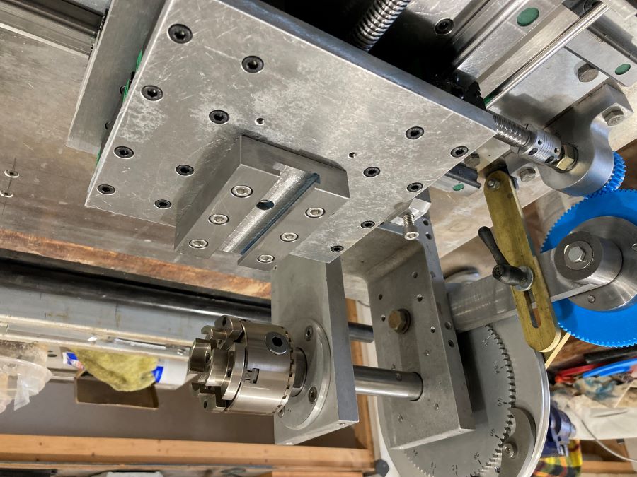
Creating the headstock and gear system
|
| |
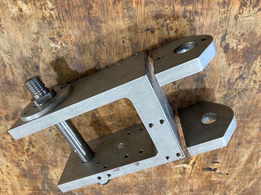
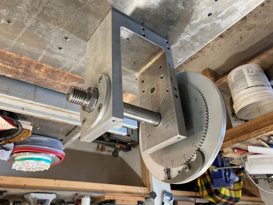
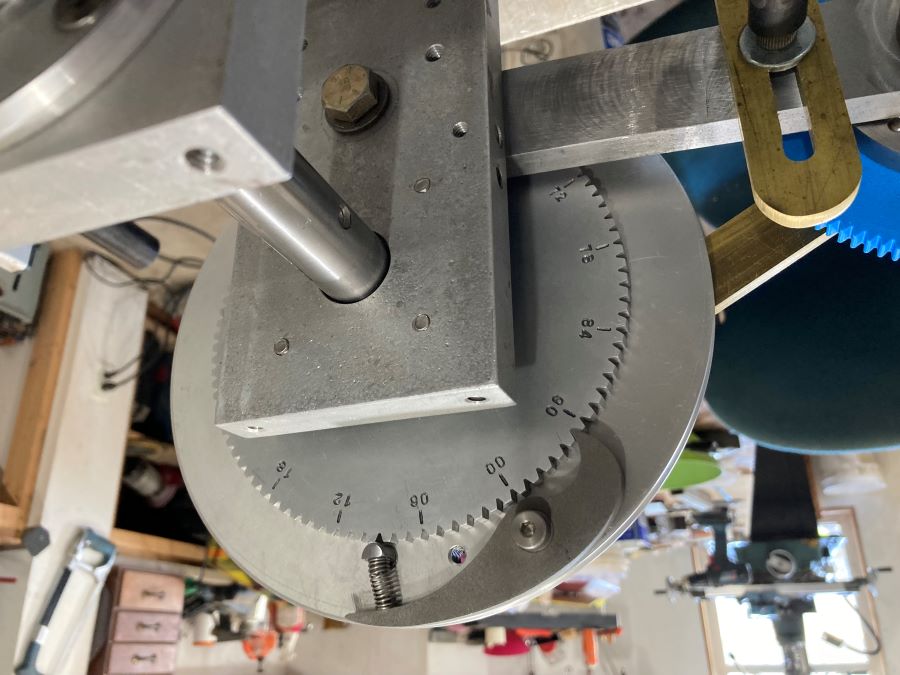
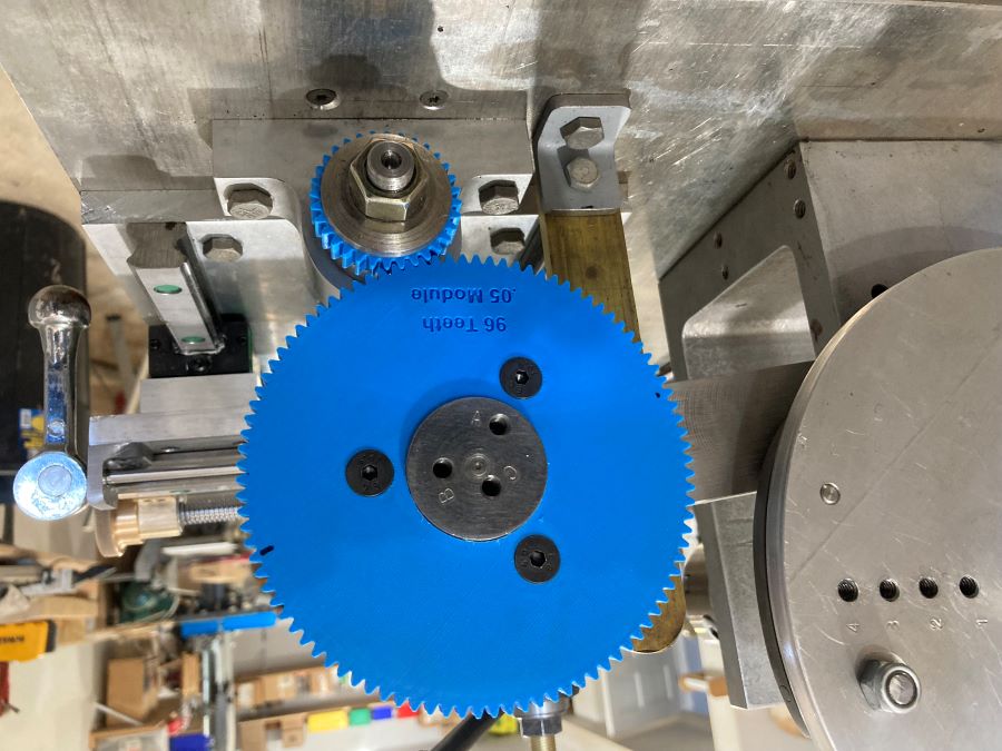
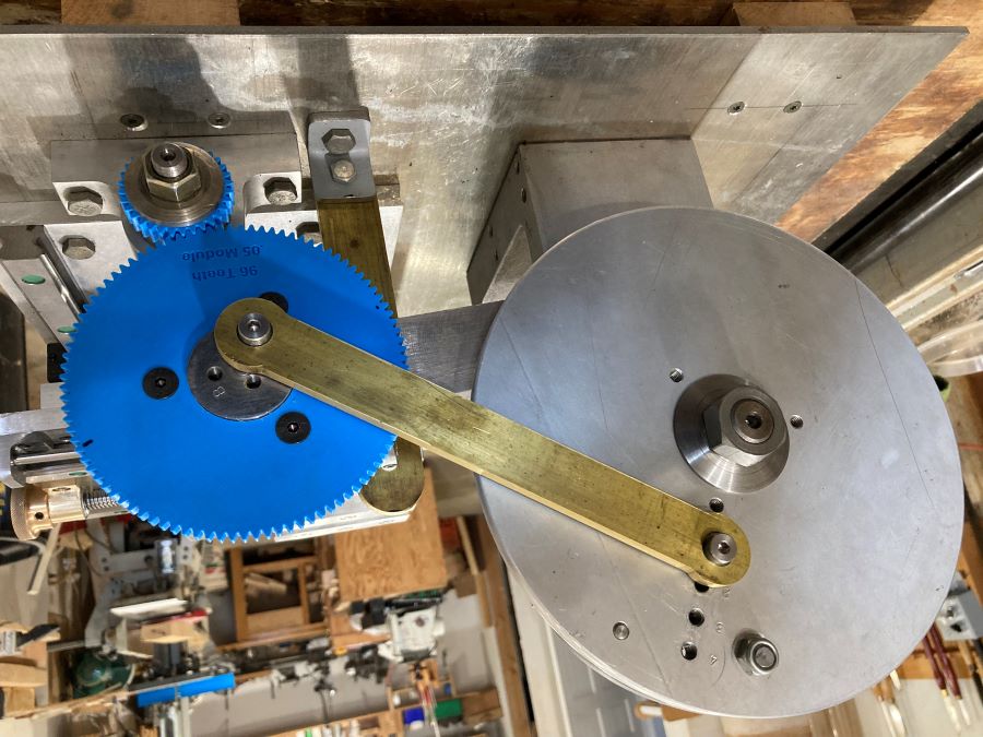
I had a headstock with spindle from a previous rose engine build that could be used with minor modifications. I cut off the two lower legs, milled the bottom flat then drilled and tapped four mounting holes in the bottom. It's mounted to a 1/4 inch aluminum plate use as the base. I turned a new hub and built the phasing wheel assemble. The phasing wheel has 96 notches, the notches were cut with a gear cutter with a dividing head on my milling machine. The phasing wheel is mounted to the hub with four bolts and turns with the spindle.
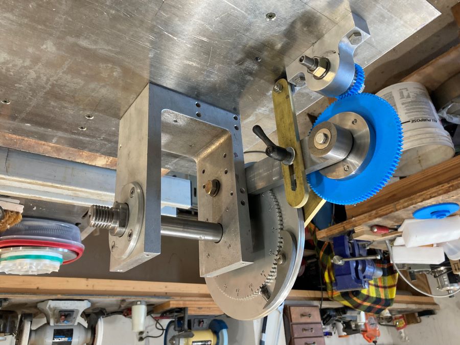
The lower gear hub was turned on my 1946 9 inch South Bend Lathe. A bronze bearing was pressed into the housing and the housing is mounted to the base. The lower gear hub will be attached to the X axis ball screw and will be turned by the ball screw. The upper gear hub was also turned on my South Bend. The hub is mounted in a swing arm with a bronze bearing, the other end of the arm is mounted to the headstock and can be adjusted up or down to properly mesh the gears. The large gear is mounted to the upper hub with three screws.
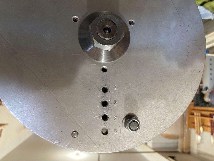
The larger pulley on the headstock has four 1/4 x 20 holes drilled and tapped 1/2 inch apart for connecting one end of the reciprocator arm, the upper gear hub has three 1/4 x 20 holes drilled and tapped, 1/4 inch, 3/8 inch and 1/2 inch from center, the other end of the reciprocator arm is connected to one of these holes.
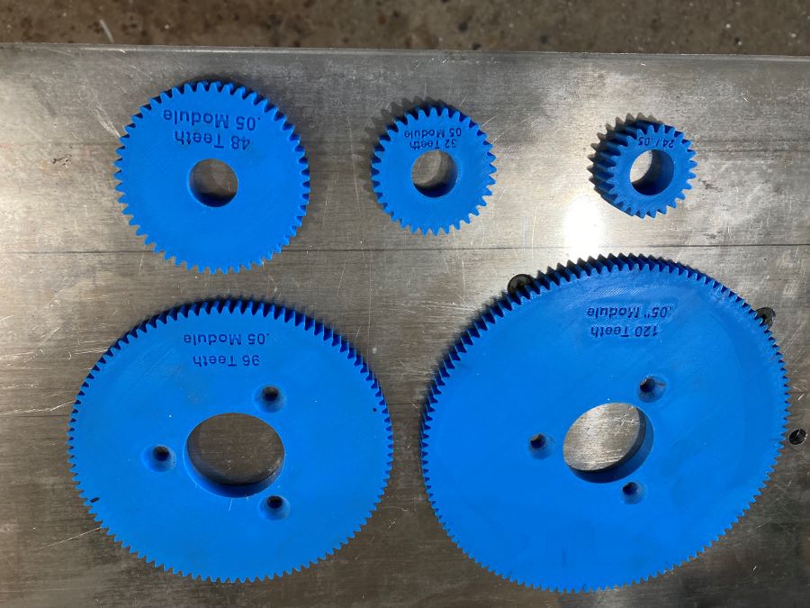
The gears are designed using FreeCAD software and printed on my 3D printer, I can create gears with any number of teeth and gear ratio and 3D print them. I’ve 3D printed five gears at this time, 120 and 96 teeth for the large gear, and 48, 32 and 24 teeth for the small gears.
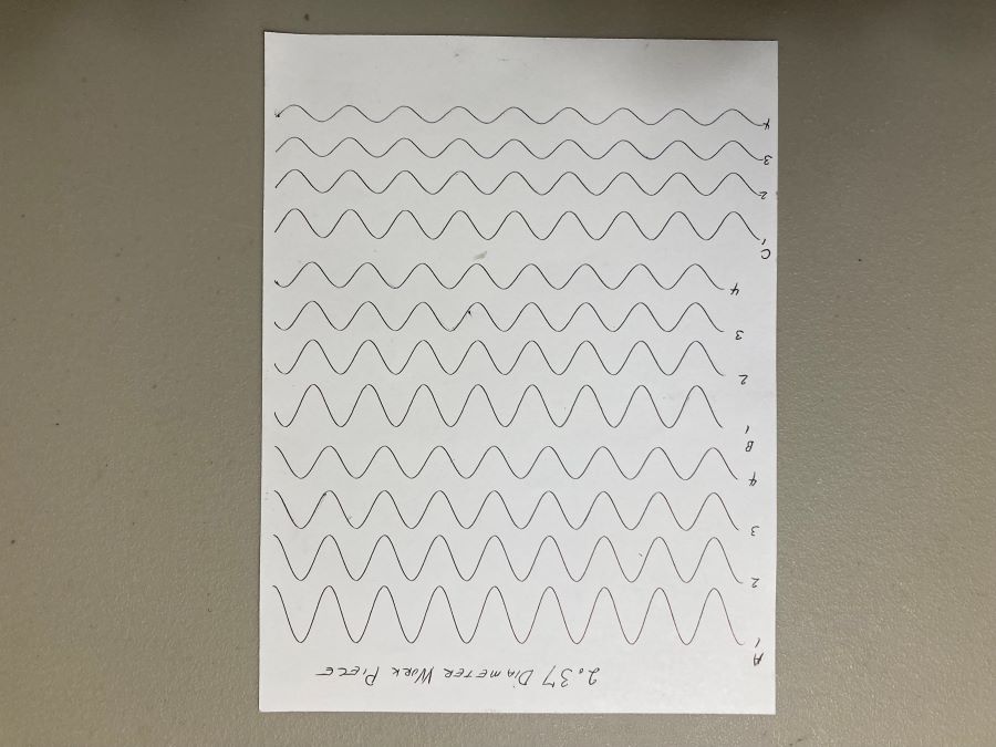
Using a 2.37 diameter paper chuck and pen, I drew sample waves going from the largest to the smallest amplitude, 12 waves total. The holes the reciprocator arm is attached to will control the amplitude of the waves. The gear ratio will control the length of the waves. The sample was run using the 96 teeth large gear and 32 teeth small gear.
|
|
|
Building the X and Y axis
|
| |
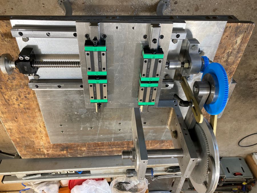
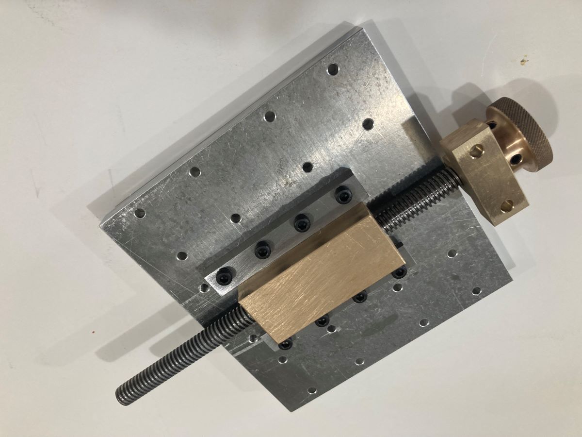
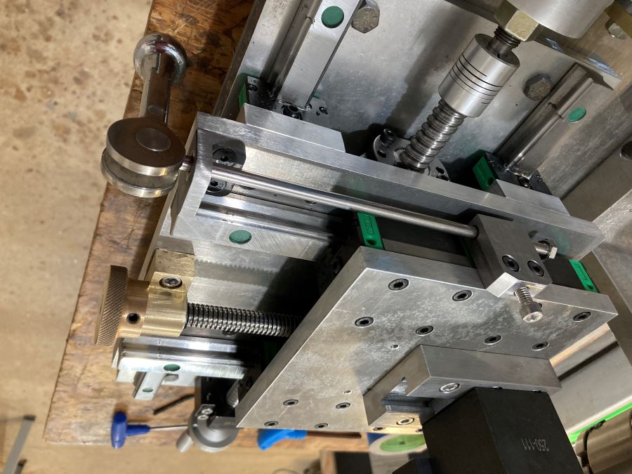
The X axis cross slide uses HGR20-400mm Linear Rails with slide blocks and a RM1605-400mm Ballscrew and nut. The rails are mounted on an 8 x 16 x 1/2 inch aluminum base which is mounted to the Reciprocator base, maybe a little over-kill but I had the aluminum. The end of the ball screw is connected to the lower gear hub with a flexible coupling. The main bearing for the ball screw is also mounted to the X axis base and the ball screw nut is mounted to the bottom of the Y axis base, a hand wheel is attached to the right end of the ball screw. To provide room for the ball screw and nut assemble two spacers had to be installed between the X axis slide blocks and the Y axis base.
The HGR20-300mm Linear Rails with slide blocks were mounted to the Y axis base, however, the ball screw was not used for the Y axis. The HGR20-300mm Linear Rails were shorten by about 2.5 inches to fit the Y axis base. Both Linear Rails kits were purchased from Amazon.
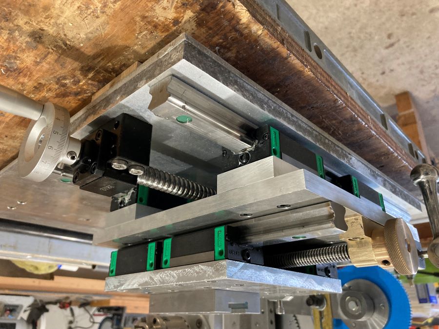
I designed the cutter adjustment mechanism (Y axis) so I can adjust the depth of cut one time and not need to change it during the process of turning the work piece. After adjusting the precise cutter depth the cut is made across the work piece then the lever is raised to retract the cutter (the Y axis is spring loaded) the cutter is returned to the starting position, the phasing wheel is advanced to the next position then the lever is lowered to return the cutter to the cutting position for the next pass.
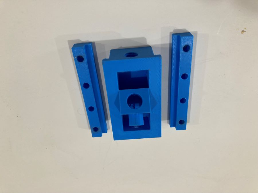
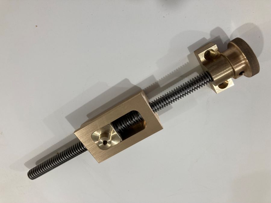
I designed the cutter adjustment mechanism, 3D printed the parts then installed the 3D printed parts on the Y axes to test and validate the design. After validating the design I built the parts with steel and brass. I'm using a 1/2 inch x 10 tpi acme threaded rod to adjust the y axis, the brass "box" is tapped at both ends for the acme rod and the small brass button in the "box" is attached to the Y axis base plate, it is spring loaded but is free to move as the Y axis base plate is retracted with lever.
To adjust the cutter, loosen the set screw on the retracting rod holder, adjust the cutter to proper depth, push the retracting rod in then tighten the set screw. The cutter assemble with be retracted when the lever is raised.
|
|
|